
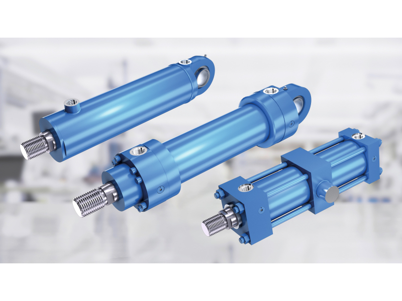
Vane pumps work through a rotating part where spring-loaded vanes slide inside a circular housing to form chambers that expand and contract. Hydraulic systems use precision components that deliver constant power for industrial use. These chambers move fluid in controlled volumes. The design prevents sudden pressure jumps seen in other types of pumps. It keeps the flow stable and supports smooth cylinder operation without uneven motion.
Rotational chamber mechanics
The pump housing holds an offset rotor that sits slightly away from the center inside the round casing. This setup forms crescent shaped gaps that change in size as the rotor moves in a circular motion. Each vane moves outward by both spring force and the spin of rotation. The vanes stay pressed against the inside surface of the cam ring and create tight chambers. These sealed spaces collect hydraulic fluid at the inlet and move it to the outlet. No fluid moves backward between the chambers during the cycle. Every full turn of the rotor moves the same amount of fluid through the pump. The reason is that the link between the rotor position and the chamber size follows a fixed design. This pattern repeats in the same way on each rotation and gives steady fluid output without variation.
Pressure compensation design
Advanced models use variable displacement systems that change pump output by adjusting how the rotor and housing move in relation to each other. Hydraulic servo units control this movement based on pressure inside the system. When pressure rises above the set point, the control system shifts the cam ring to reduce the distance between rotor and housing. This lowers the change in chamber size between maximum and minimum levels. The flow output then decreases while the pressure stays steady. The servo mechanism includes:
- Pressure sensing ports that monitor discharge line conditions in real time
- Spring-loaded actuators that balance external pressure against internal control forces
- Adjustment screws allow technicians to calibrate maximum displacement settings.
- Feedback pathways directing a small portion of pumped fluid to control chambers
- Relief valves protect the compensation system from pressure spikes during rapid load changes.
This self-regulating capability allows the pump to match flow delivery to instantaneous cylinder requirements without external electronic controllers or manual intervention by operators.
Balanced radial forces
The symmetrical arrangement of vanes around the rotor circumference distributes pressure loads evenly across bearing surfaces, preventing the lateral thrust that causes premature wear in asymmetric pump designs. Opposing vanes experience equal but opposite forces as they compress fluid, which cancels out side loading on the drive shaft and extends bearing service life. This configuration includes:
- Matched vane pairs positioned 180 degrees apart, sharing compression duties.
- Cartridge-style bearing assemblies supporting pure radial loads without thrust components
- Balanced port placement equalises suction and discharge forces.
- Shaft seals are experiencing minimal deflection during operation.
- Housing structures designed to resist internal pressure without distortion
The force equilibrium reduces mechanical stress concentrations while maintaining alignment between rotating and stationary components throughout varying operating conditions.
The consistent flow generation in vane pumps results from geometric precision that creates predictable displacement patterns combined with overlapping compression cycles that eliminate pulsation. This mechanical reliability supports hydraulic cylinder applications where steady pressure delivery ensures controlled movement.


Comments